In the power supply industry, distribution boxes are essential for reliable power distribution, circuit protection, and voltage conversion.
Equipment Solutions
For customers of mechanical equipment, our product series mainly include PLC control cabinets and HMI housings
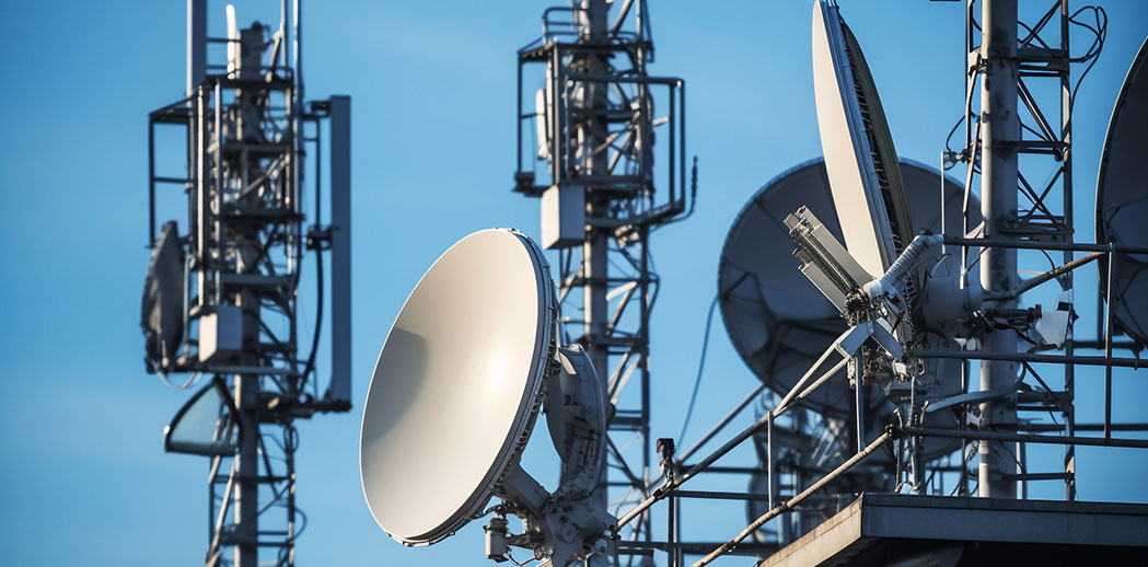
Communication Solutions
For customers of mechanical equipment, our product series mainly include PLC control cabinets and HMI housings
Security Solutions
In the field of security monitoring, we will comprehensively consider key factors such as the power requirements, power supply type, and power supply method of the monitoring equipment when designing the electrical box.
Solar Energy Solutions
In the field of security monitoring, we will comprehensively consider key factors such as the power requirements, power supply type, and power supply method of the monitoring equipment when designing the electrical box.
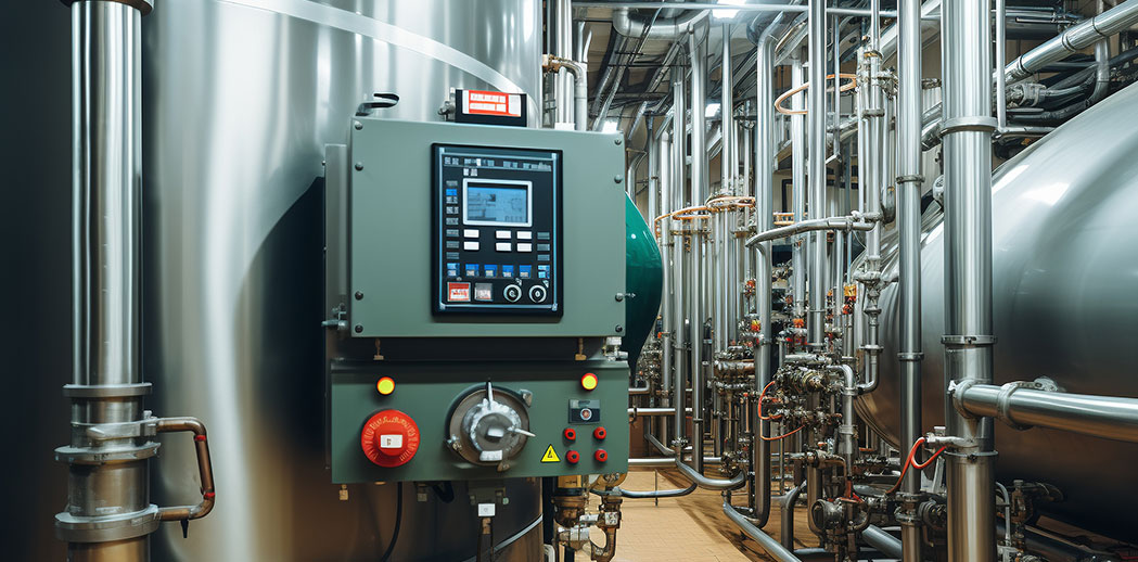
Oil & Gas Solutions
In the field of security monitoring, we will comprehensively consider key factors such as the power requirements, power supply type, and power supply method of the monitoring equipment when designing the electrical box.
Rail Solutions
Our engineering team has extensive experience in rail transit projects across China, providing custom solutions like cabinets.
Construction Solutions
Whether it is a high-rise building, commercial complex or industrial facility, our professional team will deeply analyze the characteristics of each project, including power load
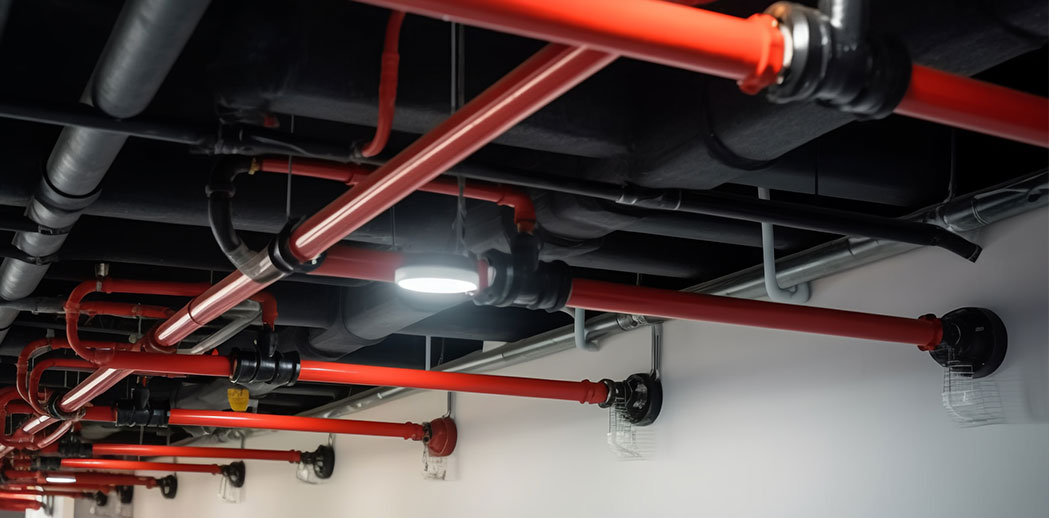
Fire Safety Solutions
Customized fire hydrants, built to your exact needs. We combine top-quality materials and strict adherence to GB50974-2014 standards to deliver hydrants that ensure safety, durability, and compliance.
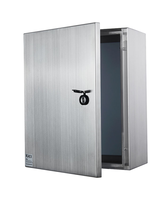
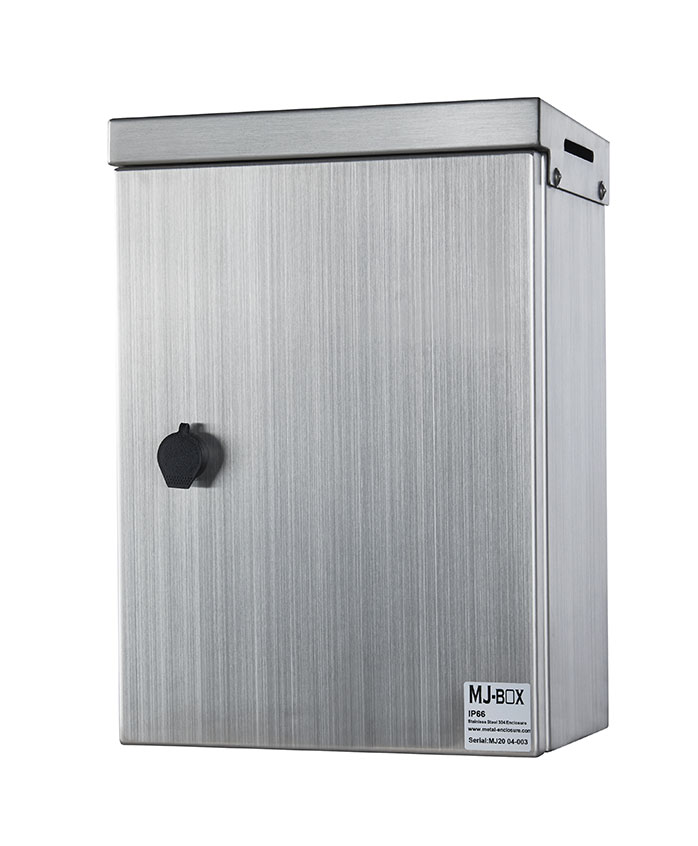
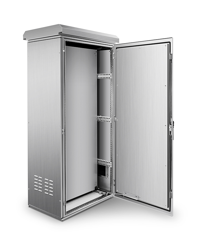
MJ-BOX offers a variety of wall-mounted enclosures in different sizes and materials. These enclosure are used of quality materials such as stainless steelcold rolled steel and Aluminum.They cover a wide range of applications. All of our enclosures are CE certified and IP66 rated.They are suitable for applications that require protection from dust, moisture and corrosion.
Explore the limits of durability and functionality with the MJ-BOX's double-sloped roof shell. The innovative removable 15° pitched roof reducing internal temperature by 20% in direct sunlight.ensures superior drainage and maintenance, preventing water accumulation and extending life.
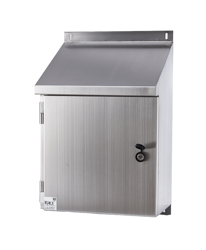
The combination of 30° inclined roof design and IP66 can better resist heavy rain and dust in the air. It is very suitable for food processing plants, construction sites, etc. to fight against airborne particles.
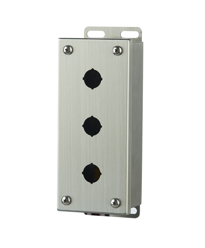
Heavy-duty stations with illuminated buttons and emergency stops. Modular design allows custom labeling and layout adjustments for CNC machines, conveyor systems, and production lines.
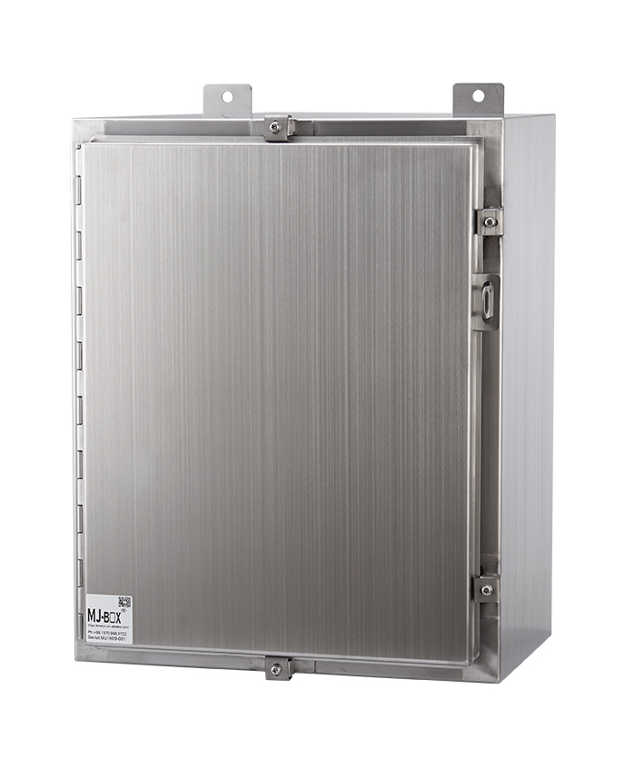
This explosion proof enclosure provides strong physical protection against impact and environmental hazards through reinforced welds and interlocking door mechanisms. It is ideal for protecting electrical components in volatile workshops or high traffic industrial areas.
Engineered for heavy-duty protection of large-scale electronics, our enclosures combine multi-material construction (steel/aluminum/composite) with adaptable mounting systems. Thrive indoors or outdoors in harsh settings—from automated warehouses to chemical plants—featuring corrosion-resistant finishes, tool-less panel access, and modular interiors for complex configurations.
Electrical Meter Box Size: Technical Guide for Proper Specification and Selection
11.26. 2025 | Electrical Box, News
Correct electrical meter box sizing guarantees safe load handling, adequate bend radius, heat dissipation, and code-compliant access. Size is driven by service ampacity, phase, circuit count, meter architecture (socket, CT, bypass), and environmental/IP requirements. Typical footprints scale with 100A, 200A, 400A, and 600A+ services, with added depth for smart modules and barriers. Installation clearances, mounting type, and future capacity must be planned. Compliance with IEC/AS/NZS standards is essential. Practical specification steps and OEM customization options are outlined next.
Key Takeaways
Size primarily follows service amp rating and calculated load; confirm demand/diversity to avoid oversizing or nuisance tripping.
Meter architecture (socket type, CT chambers, bypass, smart modules) dictates enclosure depth, jaw count spacing, and internal clearances.
Provide code-compliant working space and conductor bend radius; plan conduit entry, termination space, and utility access for maintenance.
Match environment and material to IP/NEMA rating; higher IP needs thicker walls, added gasketing, and increased enclosure depth.
Verify compliance with IEC 61439 and AS/NZS 3000; allow growth margin for future upgrades, external disconnects, and added circuits.
Why Correct Meter Box Sizing Is Critical in Electrical System Design
Although often overlooked, correct meter box sizing is pivotal to load management, safety, and service reliability in an electrical system. Selecting appropriate electrical meter box dimensions establishes adequate conductor bending radius, heat dissipation, and working space, reducing thermal stress and nuisance outages.
An undersized enclosure elevates risk of overheating, cable congestion, and nonconformity with meter box clearance requirements; an oversized unit can complicate routing, increase cost, and create coordination issues with adjacent equipment. Specifying a standard meter box size is insufficient without validating internal volume, termination geometry, and service equipment interfaces.
Proper sizing also preserves code-required access, facilitates accurate metering, and sustains enclosure integrity under fault conditions. Early allowance for future expansion and accessory integration prevents rework and preserves operational continuity. It's important to consider environmental conditions when selecting a meter box, as they dictate the material and protection ratings needed for optimal performance and longevity.
Key Parameters That Determine Electrical Meter Box Size
Meter box dimensions are primarily driven by service ampacity and calculated load, which dictate conductor size, heat dissipation, and clearance for terminations.
The number of circuits and whether the service is single- or three-phase affects gutter space, breaker or disconnect accommodation, and bend radius management.
Meter type and internal components—such as ringless vs ring-type sockets, bypass mechanisms, and CTs—set the required enclosure depth, mounting footprint, and compliance with applicable ANSI and NEMA ratings.
Amp Rating and Load Capacity
Because meter enclosures must safely accommodate conductor size, heat dissipation, and service hardware, amp rating is the primary determinant of physical meter box size and configuration.
As load capacity increases from 100A to 600A+, electrical meter box dimensions grow to provide larger conductor bending space, higher short‑circuit withstand, and adequate thermal margins.
A disciplined meter box specification ties amp rating to enclosure volume, lug spacing, and clearance for bypass hardware, without overbuilding.
Load diversity and demand factors confirm amp rating to prevent nuisance trips and thermal stress.
It is essential that licensed electricians handle the installation and maintenance of these electrical distribution boxes to ensure compliance with safety standards and minimize risks.
Number of Circuits and Service Phase
Topology dictates size: the count of outgoing circuits and the service phase (single- or three-phase) drive enclosure width, height, and depth due to terminal density, conductor bend radius, and required clearances.
More branch circuits require additional lugs or distribution space, increasing electrical meter box dimensions to maintain wire separation and labeling real estate.
Three-phase services add a phase conductor and larger neutral/ground bars, typically expanding electrical enclosure dimensions, especially in width and depth to preserve bend radii for parallel conductors.
Neutral and equipment grounding bus capacity must scale with circuit quantity. Designers should consult a meter cabinet size chart correlating circuit count and phase to compartmentalization, gutter space, and knockout patterns.
Tight layouts elevate heat and routing congestion; oversized gutters mitigate rework and future adds.
When selecting an electrical meter box, it is crucial to consider environmental conditions like dust, moisture, and temperature fluctuations to ensure the enclosure's durability and compliance with safety standards.
Meter Type and Internal Components
Architecture drives enclosure volume: the specific meter type and its internal components set minimum width, height, and depth to satisfy clearances, bend radii, heat dissipation, and code spacing.
Socket, ring-type, and ringless architectures impose different jaw counts, bypass options, and working space, directly defining electrical meter box dimensions.
Smart meters add communication modules and batteries, elevating thermal and separation needs. Current transformer (CT) chambers, surge protection devices, and test switches require isolation barriers and gutter space, often forcing a large capacity meter enclosure.
Where utility bypasses or dual-element sockets are mandated, a custom electrical enclosure size becomes unavoidable.
Meter form and socket/bypass type dictate lateral clearance
CT chamber volume and cable bend radius drive depth
SPD footprint plus conductor routing increases height
Smart-meter radios need a thermal derating margin
Utility working space rules fix front and side offsets
Effective environmental seals are crucial for protecting electrical meter boxes from contaminants and temperature fluctuations, ensuring long-term reliability in high-temperature settings.
Standard Electrical Meter Box Dimensions and Configurations
Standard meter box offerings align to common industry sizes (e.g., single-position residential vs multi-position commercial), each tied to specific service amperage and socket configurations.
Selection balances internal working clearance for conductors, terminations, and bypass hardware against required external clearances for code-compliant access and serviceability.
Enclosure depth is evaluated with heat dissipation needs, ensuring ventilation provisions prevent hotspots without compromising enclosure ratings.
Common Industry Sizes
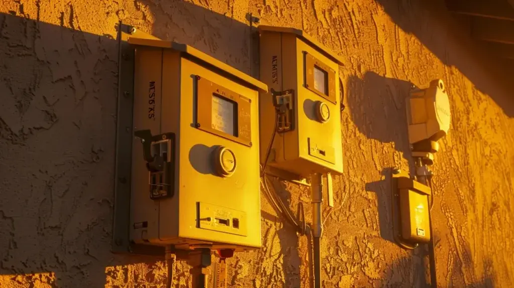
Across residential, commercial, and industrial applications, electric meter boxes are produced in standardized footprints to match wall-mounted and recessed installations, service ampacities, and utility metering hardware. Common ranges for electrical meter box dimensions align with utility socket patterns, conduit entry spacing, and NEC working space, enabling predictable coordination with service risers and panels.
Typical wall-mounted meter box size selections scale with meter count, bypass type, and fault duty, while industrial meter box size options enlarge for CT compartments, heavier-gauge steel, and multi-meter arrays.
Residential: single-meter, 10000 A, compact wall units; shallow recessed variants for façade alignment.
Small commercial: 20000 A sockets; allowance for lever-bypass and larger knockouts.
Multi-tenant: stackable meter centers, modular widths/heights.
Light industrial: CT-ready enclosures, deep profiles, expanded wiring gutters.
Heavy industrial: large CT/PT sections, external disconnect integration, robust mounting flanges.
Internal vs External Clearance
Internal spacing for cable routing must be sized to accommodate conductor bend radii, neutral/ground bars, and breaker bodies without inducing pinched insulation or exceeding terminal fill. Electrical meter box dimensions should allocate dedicated wireways alongside termination points to maintain separation, labeling visibility, and service loop discipline. Overcrowding elevates thermal and fault risk and complicates meter exchanges. Junction boxes safely enclose wire connections, preventing short circuits and reducing electrical fire risks. External clearance requirements define safe approach and working envelopes for inspection, testing, and maintenance. Adequate front, side, and door-swing space guarantees unobstructed access to seals, bypasses, jaws, and labeling, enabling torque verification and meter removal under utility supervision.
Properly coordinated internal and external clearances reduce rework, speed commissioning, and sustain code-conforming serviceability.
Enclosure Depth and Ventilation
Deeper meter enclosures provide two primary benefits: compliant conductor bend radii and improved heat rejection. Increased depth enables conductors to sweep to terminals without kinking, preserving the specified cable bending radius and minimizing insulation stress.
Thermally, added volume and airflow paths lower component temperatures, stabilizing meter accuracy and extending service life, particularly in a weatherproof meter box enclosure where solar load elevates internal heat. Effective heat sink design and airflow optimization are essential for mitigating overheating risks, ensuring reliable and efficient operation of the electrical meter box.
Select electrical meter box dimensions that allow minimum 82× conductor diameter bend radius at all terminations.
Reserve rear and side plenum space to separate service loops from heat sources.
Use louvered or baffled vents with insect screens; avoid compromising NEMA/IEC ingress ratings.
Prefer matte, light-colored finishes to reduce solar gain; include sunshades where exposed.
Verify depth supports meter bypass hardware without obstructing convective airflow.
Environmental and Material Considerations Affecting Size
Environmental conditions dictate enclosure volume, with outdoor installations requiring larger clearances, weatherproof gasketing, and heat dissipation space than indoor units. Specified IP ratings and mounting type (surface, flush, or pedestal) influence enclosure depth, sealing features, and allowable cable bend radius, thereby altering overall size. Material selection—steel, aluminum, or nonmetallic—affects wall thickness, corrosion resistance, thermal expansion, and structural rigidity, which in turn determines minimum enclosure dimensions for code-compliant wiring and hardware. It's essential to ensure compliance with industry standards such as NEMA and IP ratings to guarantee the safety and performance of the enclosure.
Outdoor vs Indoor Installations
Although meter sockets share core components, outdoor installations typically require larger enclosures than indoor units to accommodate added protection against weather and contaminants.
An electrical meter box dimensions guide should account for added space due to insulation, waterproofing, and ventilation layers. Outdoor electrical meter box size grows with drip shields, gasketing, drainage paths, and reinforced hinges; an ip66 electrical enclosure often dictates deeper bodies and wider clearances to prevent condensation and allow airflow without ingress.
Allow volume for rainhoods, drip edges, and overhangs without infringing conduit bend radii.
Increase depth to offset insulation panels and cable manager spacing.
Reserve clearance for screened vents and condensate channels.
Upsize to integrate sunshades and thermal barriers limiting enclosure heat rise.
Indoor units can minimize depth and width where contaminants and precipitation are controlled.
Outdoor meter box installations often require compliance with protection standards like IP66 to ensure robust protection against environmental elements.
IP Rating and Mounting Type
Outdoor sizing considerations extend directly to ingress protection and mounting, as higher IP ratings (IP65–IP67) and different mount styles drive enclosure dimensions and construction. To achieve IP65–IP67, meter box design standards typically require thicker walls, deeper lids, labyrinth gaskets, and reinforced seams, which increase electrical meter box dimensions and reduce usable internal volume. Hinges, latches, and cable glands scale accordingly, impacting footprint and door swing clearances. Mounting type further dictates size envelopes: wall-mount units need larger backpan spacing for heat dissipation and conductor bend radius; pole-mount kits add brackets and standoff depth; recessed installations reserve side and rear tolerances for masonry and conduit entry. A stainless steel electrical box meeting these ratings often grows in depth to accommodate gasketing compression, gland knockouts, and bracket load paths while preserving meter socket clearances and service accessibility. Certification is conducted by third-party laboratories to validate IP ratings, ensuring that the enclosure meets the necessary protection standards.
Material Selection
Material choice directly influences enclosure dimensions, tolerances, and mounting loads because mechanical strength, corrosion resistance, and thermal behavior vary across stainless steel, galvanized steel, and polycarbonate. These differences propagate into electrical meter box dimensions and electrical distribution box dimensions, dictating wall thickness, fastener sizing, and bracket spacing. Stainless steel permits thinner panels and tighter tolerances but increases mass, raising anchorage requirements. Galvanized steel balances cost and strength with moderate corrosion resistance. Polycarbonate reduces weight and enables larger spans, yet needs greater section depth for stiffness and UV-stabilized grades. Specify allowable deflection to set panel gauge or ribbing. Derate size for thermal expansion; adjust hole clearances. Calculate substrate pull-out for mounting loads. Align enclosure mass with seismic/wind demands. Use a custom meter box enclosure when the cable bend radius or accessories force larger depth. When selecting materials for corrosive environments, consider using stainless steel or fiberglass-reinforced polyester for superior resistance and durability.
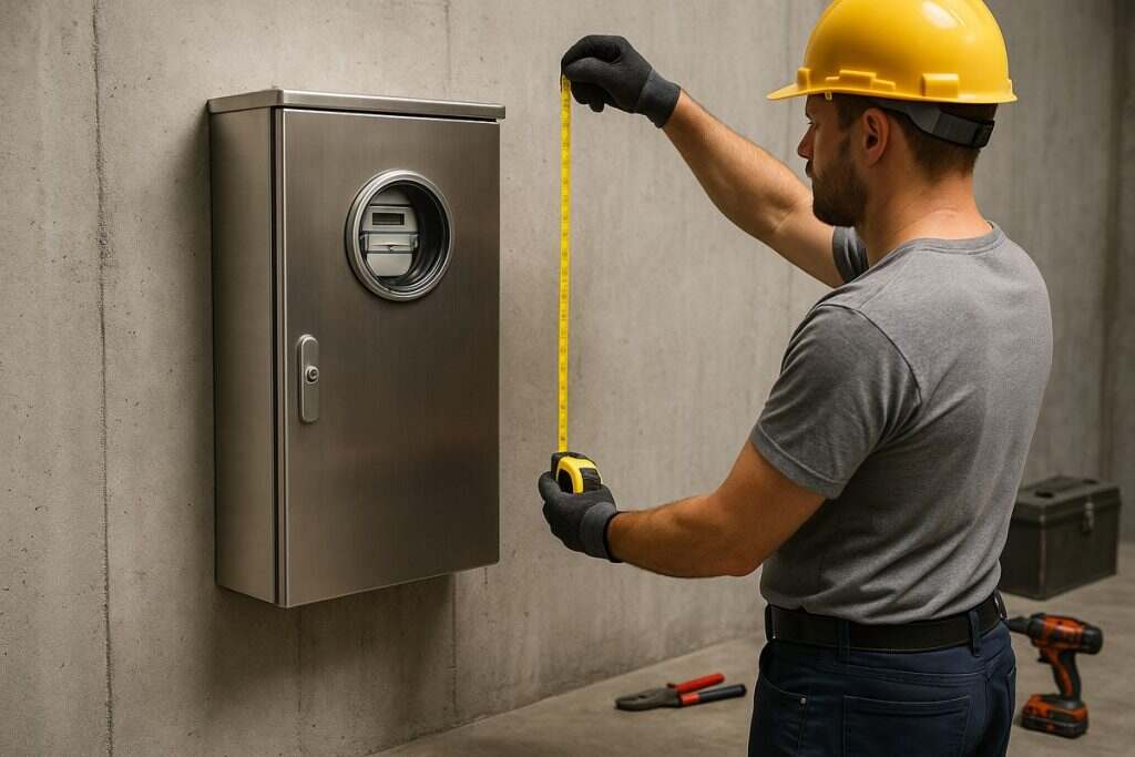
Installation Guidelines and Spatial Planning
Installation strategy determines meter box footprint and clearances, whether mounted on a wall, on a pole, or on a freestanding pedestal.
Spatial planning must reserve code-compliant working space for access and maintenance, including height, lateral clearance, and meter-to-meter separations.
Box sizing should account for conduit entries, feeder bending radii, and termination space to maintain enclosure ratings and minimize strain on conductors.
Wall, Pole, or Freestanding Installations
Whether mounted on a wall, utility pole, or freestanding pedestal, meter box placement must satisfy clearance, mounting height, accessibility, and environmental protection requirements defined by local codes and aligned with IEC/AS/NZS guidance.
Selection begins with the electrical meter box size and verified meter box dimensions; reference an electrical meter box dimensions chart to validate envelope, conduit entry, and bending radii. Structural anchorage, corrosion resistance, and ingress protection are non-negotiable.
Wall: fix to solid substrate with expansion anchors; maintain damp-proof offsets and UV-stable seals.
Pole: use banding or through-bolts; add standoff brackets to reduce vibration and water tracking.
Freestanding: specify pedestals with rated foundations and cable pit coordination.
Heights: set lower edge within prescribed ranges; confirm reader sightlines.
Clearances: observe side/top working envelopes and utility service drop approach paths.
Accessibility and Maintenance Space
Although enclosure size drives placement, accessibility and maintenance space determine code compliance and serviceability. Clearances must accommodate minimum service space for utility meter reading, ventilation, and lock mechanisms.
The mjbox or meter box should be mounted at a readable height with unobstructed frontal access, allowing safe door swing and tool use without encroachment from vegetation, fences, or building elements.
Working space depth and width should permit operation of bypass handles and locks, and removal of covers without interference. Ventilation openings require free airflow; avoid recesses that trap heat.
Provide firm, level footing for technicians to stand safely. Maintain tamper seals visible and reachable without disassembly.
Grouped installations must preserve individual access envelopes so each enclosure can be isolated, serviced, and inspected independently.
Integration with Conduits and Feeders
With clear working space established, conduit entries and feeder routes must be laid out to protect bending radii, maintain enclosure integrity, and support future capacity.
Meter box sizing should anticipate present conductors and reserve area for additional knockouts, hubs, and chase nipples. Entry points are best clustered to minimize crossovers and preserve wire management, while leaving unobstructed paths to line/load terminals and the grounding bar.
Penetrations should align with factory knockouts or hubs to maintain the enclosure rating and avoid field damage. Feeder conduit size dictates required gutter space for terminations and stress relief. Spatial allowances must reflect pull-length criteria and segregation of services.
Reserve dedicated zones for cable entries
Align conduit with factory knockouts
Maintain minimum bending radii clearances
Provide spare knockouts for expansion
Preserve straight-in approaches to terminals
How to Specify the Right Size for Your Project
Correct sizing begins with a quantified load and equipment assessment, including service amperage, feeder count, conductor sizes, device footprints, and required clearances.
Capacity should include documented headroom for future circuits, larger feeders, and accessory modules, expressed as percentage expansion margin and spare pole/space allocations.
Final dimensions and ratings must be verified against NEC/ANSI/UL listings and local utility specifications to guarantee code compliance and utility acceptance.
Conduct a Load and Equipment Assessment
A rigorous load and equipment assessment establishes the service rating, enclosure size, and mounting method required for a meter box. The evaluator quantifies connected load, coincident demand, and starting currents to determine service amperage, short-circuit duty, and thermal dissipation.
These parameters drive enclosure dimensions for conductor bending space, device clearances, and heat management, and they dictate whether wall, pedestal, or recessed mounting is appropriate for structural and access constraints.
Inventory all loads by phase, voltage, and duty cycle; calculate diversified demand per applicable code methodology.
Confirm service rating (A) and fault current; size bus, lugs, and jaws accordingly.
Determine conductor count, size, and bending radius to set box width, height, and depth.
Specify required accessories (bypass, hubs, CTs) and verify space claims.
Match enclosure and mounting method to site conditions and utility requirements.
Include Future-Proofing and Expansion Margins
Although the load study sets a minimum enclosure, a prudent specification adds growth margins for foreseeable upgrades and technology integration. The meter box should accommodate reserve space for emerging loads such as EV charging, rooftop PV interconnections, battery inverters, and automation hardware (gateways, relays, CTs).
Specify increased gutter space, additional breaker or disconnect mounting area, and spare conduit knockouts to avoid enclosure replacement.
A practical approach is to allocate 250% spare cross-sectional wiring space and at least two spare termination points per phase and neutral. Select enclosures with deeper profiles to maintain bend radii for larger conductors anticipated with EVSE or storage upgrades.
Provide segregated DIN rail or backplate real estate for control devices. Guarantee physical clearance for future external disconnects and generation metering, and include labeled spare conduits to strategic locations.
Verify Compliance with Standards
Before finalizing dimensions, compliance must be validated against governing standards so the enclosure’s physical size, clearances, and component layout meet mandated performance and safety criteria.
The specified meter box must align with IEC 61439, AS/NZS 3000, and relevant local regulations to validate busbar spacing, segregation, ingress protection, and thermal limits. Dimensional choices must guarantee safe working space, door swing, and conductor bending radii while accommodating utility metering requirements and labeling.
Confirm enclosure rating and construction per IEC 61439, including short-circuit withstand and temperature rise.
Validate wiring methods, clearances, and RCD/earthing arrangements per AS/NZS 3000.
Cross-check local codes for working space, mounting heights, and access.
Verify IP/NEMA ratings for site environment and UV/corrosion resistance.
Document conformity with certificates, data sheets, and inspection records.
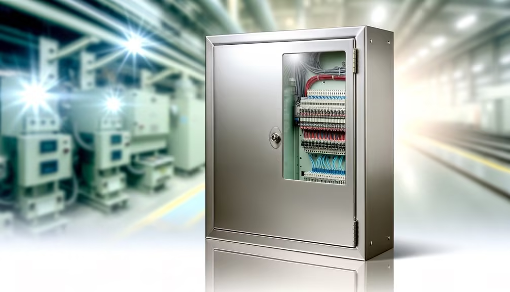
Custom Meter Box Sizing and OEM Capabilities from MJBOX
From single-unit residential sockets to multi-meter industrial arrays, MJBOX engineers size and manufacture meter boxes to precise electrical and environmental specifications.
Their OEM program scales from prototype to volume, delivering IP66/NEMA 4X-rated enclosures with ISO/UL/CE compliance and documented FAT/QA traceability. Engineers tailor form factor, bus and jaw layouts, bypass options, grounding schemes, and heat dissipation to utility requirements and NEC/ANSI C12 interfaces, including HMI apertures and PLC integration when needed.
Material choices include coated steel and corrosion-resistant alloys with gasket systems validated for outdoor duty. Options extend to solar-ready inputs, security monitoring, power architectures, and fire-safety interface provisions per GB50974-2014.
Fortune 500 deployments confirm durability. Global support across 37 countries guarantees consistent lead times, controlled tolerances, and certification-ready documentation.
How Do Utilities Approve Meter Box Models Before Installation?
Utilities approve meter box models via utility-approved lists after verifying ANSI C12/UL listings, enclosure NEMA ratings, short-circuit ratings, bypass provisions, jaw compatibility, tamper resistance, grounding, and labeling. Vendors submit data sheets and samples; utilities perform audits, type tests, and field trials.
What Tamper-Evident Features Are Available for Meter Boxes?
Tamper-evident features include utility seals, ring or lever seals, lockable hasps, breakaway tabs, anti-pry flanges, intrusion switches, sealed bypass covers, tinted/UV-resistant windows, audit logs, and tamper-indicating labels—revealing any unauthorized access while preserving chain-of-custody and compliance traceability.
How Are Meter Boxes Maintained in Extreme Weather Regions?
They are maintained through scheduled inspections, weatherproof NEMA enclosures, gasket integrity checks, anti-corrosion coatings, drainage and sealing audits, torque verification of terminals, UV-resistant covers, heater/vent kits, tamper-seal assessments, grounding tests, and immediate remediation of cracks, rust, moisture ingress, or insulation degradation.
Which Standards Govern Meter Cover Interchangeability and Compatibility?
ANSI C12.7 governs meter cover interchangeability and compatibility; broader meter performance and safety align with ANSI C12 series. As the saying goes, measure twice, cut once—specifiers verify socket dimensions, sealing methods, jaw alignment, enclosure ratings, and utility acceptance.
When Is a Bypass Mechanism Required for Service Continuity?
A bypass mechanism is required when utilities or electricians must maintain service during meter testing, replacement, or maintenance, especially for critical loads, multi-tenant services, or code/utility mandates. It guarantees continuity, safety isolation, and minimizes outage risk and operational disruption.
Conclusion
In the end, correct meter box sizing is not optional but foundational—what is design without compliance, capacity, and clearances in lockstep? By aligning utility standards, NEC/ANSI provisions, enclosure ratings, and spatial allowances for conductors and accessories, specifiers minimize risk and rework while ensuring maintainability. Environmental exposures, mounting height, and working space guide enclosure selection and placement. When standard configurations fall short, tailored OEM solutions from MJBOX bridge gaps, future-proofing installations and safeguarding performance across diverse project conditions.
We are deeply committed to excellence in everything we do, ensuring meticulous control over our products to deliver unparalleled quality and outstanding service to our customers.